Physical Lighting Simulation Standards
Achieving photorealistic automotive renders hinges on the transition from arbitrary light placement to the simulation of real-world optical behavior. While many users default to simple emissive geometry to brighten a scene, professional workflows prioritize IES light profiles to replicate the specific falloff and intensity patterns of actual studio hardware. According to Autodesk documentation, VRED enables this by allowing the import of IES files, which ensures that headlight and LED array visualizations behave according to their physical specifications rather than artistic approximation.
A common failure mode in studio lighting is the over-reliance on a single HDRI for both reflection and illumination. Field discussions on platforms like Reddit often highlight that relying solely on an environment map results in muddy body lines and a lack of crisp specular highlights. To correct this, practitioners frequently layer targeted area lights over the base HDRI, using the environment map for global reflections while reserving area lights to define the specific curvature of fenders and beltlines. This hybrid approach prevents the flat, synthetic look that often plagues entry-level renders.
When simulating studio soft-boxes, the distinction between primary highlights and fill light is critical for maintaining physical accuracy. Use emissive geometry only for secondary fill or subtle rim lighting, as these lack the precise light-profile data required for high-end automotive work. Rely instead on dedicated area lights for primary highlights, which provide the necessary control over light decay and shape. For complex materials like carbon fiber or metallic paint, ensure your setup accounts for subsurface scattering, a feature specifically optimized in VRED Professional to simulate how light penetrates and interacts with clear-coat and paint flake layers.
Balancing global illumination requires a nuanced use of skylight systems in tandem with localized area lights. If your render appears washed out or lacks depth, it is often because the global illumination is overpowering the localized light sources. One effective technique involves lowering the intensity of the environment map and manually placing area lights to draw the viewer's eye to the vehicle's design language. This manual intervention mimics the process of a studio photographer adjusting physical strobes to carve out the form of the car against a dark background.
| Lighting Technique | Primary Application | Operational Benefit |
| IES Profiles | Headlights/LEDs | Physical intensity accuracy |
| Area Lights | Body Highlights | Defined specular control |
| Emissive Geometry | Secondary Fill | Soft, ambient light contribution |
| Subsurface Scattering | Clear-coat/Paint | Realistic flake/depth simulation |
| Rayfile Integration | Complex Optics | Projector headlight simulation |
To refine your current setup, compare your existing render against a reference photograph of a studio-lit vehicle, focusing specifically on the shape and falloff of the highlights. If your digital highlights are uniform or lack the characteristic soft-edge decay of a physical soft-box, replace your emissive planes with area lights and apply an IES profile to your light sources. Verify these adjustments by rendering a single frame with a high-contrast metallic material to ensure the light interaction accurately captures the paint flake depth.
Workflow Speed and Hardware Constraints
Choosing between VRED and KeyShot often comes down to the scale of your CAD data and the specific hardware available in your studio. KeyShot relies on a CPU-based real-time engine that prioritizes immediate visual feedback, allowing designers to tweak materials and light sources without waiting for a full ray-traced pass. This architecture makes it a preferred choice for independent designers who need to iterate on aesthetic concepts rapidly. As of June 2026, the introduction of native Apple Silicon support in KeyShot Studio 2026.2 has further shifted the hardware calculus, enabling high-performance rendering on mobile workstations that were previously bottlenecked by thermal constraints.
Conversely, VRED is engineered for high-fidelity management of massive datasets, making it the industry standard for enterprise automotive workflows where variant management and complex assemblies are the norm. While KeyShot excels at "drag-and-drop" environment workflows that minimize time spent on light-linking, VRED provides the granular control necessary for large-scale production environments. Practitioners on design forums often point out that VRED requires a more robust workstation configuration to handle its professional-grade ray-tracing and multi-pass rendering capabilities effectively, whereas KeyShot’s more forgiving engine allows for acceptable results on lighter hardware setups.
| Feature | KeyShot | Autodesk VRED |
|---|---|---|
| Engine Architecture | CPU-based real-time | Enterprise-grade ray-tracing |
| Primary Strength | Rapid aesthetic iteration | Large-scale CAD management |
| Hardware Optimization | Native Apple Silicon support | High-end multi-core/GPU clusters |
| Workflow Style | Drag-and-drop simplicity | Complex variant management |
A common failure mode for teams transitioning between these tools is attempting to replicate a VRED-style multi-pass workflow inside KeyShot without accounting for the differences in how each engine handles scene overhead. If your project involves thousands of individual parts or complex product configurations, the overhead in VRED is a necessary trade-off for the stability it provides during final output. If you are currently evaluating your studio's hardware, check your specific workstation's benchmark scores against the latest June 2026 requirements for your chosen engine before committing to a long-term project file structure.
To determine which tool fits your current pipeline, perform a side-by-side test using a single complex assembly from your library. Measure the time required to import the data, apply basic materials, and achieve a stable, noise-free preview.
Virtual Camera Calibration Techniques
Professional automotive renders rely on virtual camera focal lengths between 50mm and 85mm to maintain accurate vehicle proportions. Amateur work frequently suffers from wide-angle distortion, where focal lengths below 35mm artificially stretch the front fascia and exaggerate the hood length, effectively ruining the designer's intent. By locking your virtual camera into the 50mm–85mm range, you mimic the physical optics used in high-end automotive photography, ensuring the car’s silhouette remains true to its CAD geometry.
Aperture control serves as your primary lever for managing depth of field, which dictates how much of the vehicle remains in sharp focus. For full-vehicle hero shots, practitioners typically set apertures between f/8 and f/16. This range provides enough depth to keep the entire length of the car crisp while allowing for a subtle, natural fall-off toward the background. Using an aperture wider than f/4 often results in a miniature or toy-like appearance, as the shallow depth of field creates a sense of scale that is physically inconsistent with a full-sized vehicle.
Camera height is frequently overlooked, yet it remains the most critical factor for grounding a render in reality. One common mistake reported in design forums is placing the camera at ground level to achieve a dramatic angle; however, this rarely reflects how a human observer actually perceives a car in a studio environment. Aligning the virtual camera height with the eye level of a standing or seated observer—typically between 1.0 and 1.5 meters—creates a more relatable and professional perspective. This alignment prevents the unnatural, distorted look that occurs when the camera is positioned at the level of the tires.
Calibration must be treated as a holistic process where the camera settings and the HDRI environment are adjusted in tandem. If your HDRI environment features high-contrast light sources, such as overhead studio softboxes, ensure your camera’s focal plane is aligned to capture the reflection of these lights across the curved body panels. Misalignment here often leads to "floating" highlights that fail to follow the car's character lines, breaking the illusion of a physical studio shoot. Always verify these reflections by rendering a test frame with a high-contrast metallic material to confirm that the light interaction behaves predictably across the vehicle's surfaces.
| Parameter | Standard Setting | Primary Objective |
| Focal Length | 50mm – 85mm | Minimize perspective distortion |
| Aperture | f/8 – f/16 | Control depth of field/scale |
| Camera Height | 1.0m – 1.5m | Human-eye perspective |
| Focus Target | Center of B-pillar | Ensure uniform sharpness |
To refine your next render, set your camera to 70mm, lock the aperture at f/11, and adjust the camera height to 1.2 meters before making any final lighting tweaks. This baseline configuration provides the most neutral starting point for evaluating how your chosen materials and light profiles interact with the vehicle's form.
Multi-Pass Rendering Strategies
Multi-pass rendering is the industry standard for decoupling the complex interaction of light from the underlying geometry, allowing you to manipulate reflection, shadow, and diffuse layers independently during post-production. By isolating these passes, you avoid the time-intensive requirement of re-rendering an entire scene simply to adjust the intensity of a highlight on a specific body panel or to deepen the shadows cast by a wheel arch.
When working with aftermarket body kits or custom spoilers, utilize light-linking to restrict the influence of specific light sources to individual components. This technique prevents light bleed, where a highlight intended for a hood scoop inadvertently washes out the subtle curvature of the fender. Practitioners on specialized automotive design forums frequently report that failing to implement light-linking leads to a flat, synthetic appearance that betrays the digital nature of the render.
AI-assisted denoising has become a critical component of modern pipelines, effectively reducing the compute time required to achieve a clean image by eliminating noise in the early stages of the render. According to documentation from both Autodesk and Luxion, this integration preserves high-frequency surface detail like clear-coat orange peel or metallic paint flake, which were traditionally lost in aggressive manual denoising processes.
To maintain an efficient workflow, always generate a material ID pass, often referred to as a clown pass, alongside your primary beauty render. This pass assigns a unique, flat color to every distinct material or component in your scene, enabling near-instantaneous selection in software like Adobe Photoshop or Foundry Nuke. This approach eliminates the need for tedious manual masking when you need to color-correct a specific trim piece or change the finish of a brake caliper.
| Technique | Primary Benefit | Post-Production Utility |
| Multi-Pass Separation | Layered control | Independent reflection/shadow tuning |
| Light-Linking | Geometry isolation | Prevents light bleed on custom parts |
| AI-Assisted Denoising | Compute efficiency | Retains high-frequency surface detail |
| Material ID Pass | Selection speed | Instant masking of complex geometry |
For your next project, perform a test render using a single complex assembly from your current design library. Compare the time required to adjust reflection intensity using a multi-pass workflow versus re-rendering the entire scene with modified light settings. Use this delta to establish a baseline for your studio's specific hardware performance.
Case Study: Tuning Project Visualization
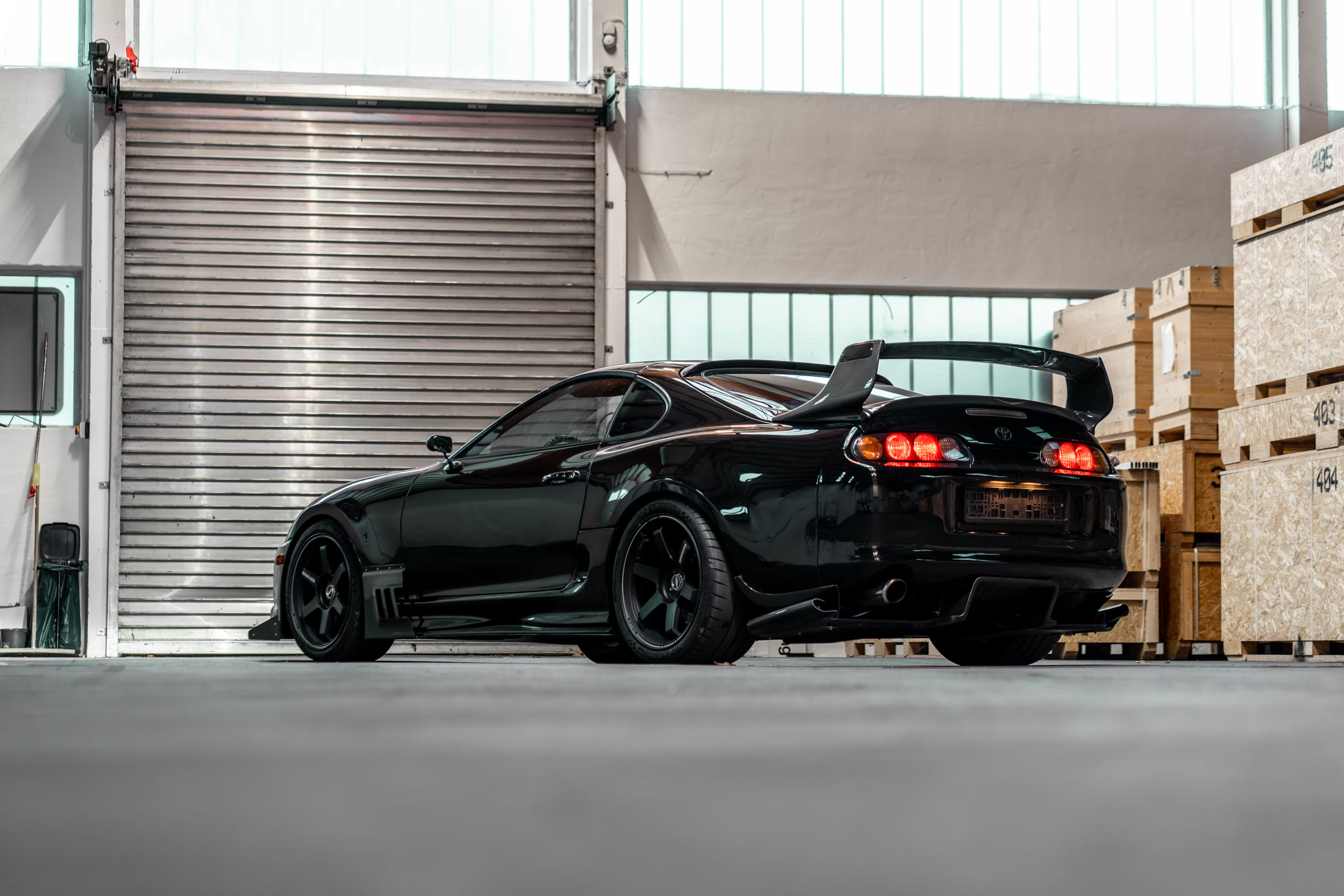
When visualizing a custom wide-body kit, the primary failure mode is treating the vehicle as a static object rather than a complex surface that demands specific light interaction. Most hobbyist renders rely on a single High Dynamic Range Image (HDRI) for both global illumination and reflections, which inevitably results in muddy, washed-out wheel arches where the aggressive geometry of the flares disappears into the shadows. For professional-grade results, you must move beyond the environment map and implement a multi-pass lighting strategy that prioritizes surface definition over global ambient light.
To achieve the crisp, high-contrast highlights required for marketing-tier automotive imagery, place targeted area lights at 45-degree angles relative to the wheel arches. This technique forces the renderer to calculate distinct specular highlights along the edges of the wide-body panels, effectively separating the kit from the base bodywork. The additional setup and computation time is the industry-standard path for ensuring that custom body modifications are legible and impactful in final portfolio work.
For projects involving advanced lighting hardware, such as custom projector headlights, leverage rayfile integration to simulate realistic light projection patterns. Unlike standard emissive geometry, which merely glows, rayfiles allow the light to interact physically with the ground plane and surrounding environment. This adds a layer of show-car realism that is difficult to replicate with post-production compositing. When you need to adjust the intensity of these specific light sources, a multi-pass workflow allows for independent control, avoiding the need to re-render the entire scene for minor tweaks.
The following table outlines the trade-offs between standard environment-based lighting and the professional multi-pass technique for a typical wide-body tuning project.
| Lighting Strategy | Primary Benefit | Render/Setup Time | Best Use Case |
| Single HDRI | Speed | 15 Minutes | Internal concept review |
| Multi-Pass Area Lights | Surface Definition | 60 Minutes | Marketing/Portfolio |
| Rayfile Integration | Physical Realism | 45 Minutes | Headlight/Optic focus |
Practitioners on design forums frequently note that the most common regret in automotive visualization is the over-reliance on automated lighting presets. If you find your wide-body kit lacks definition, verify your scene by isolating the reflection pass; if the highlights are not tracing the body lines, your light sources are likely too diffuse. To refine your process, perform a side-by-side test using a single complex assembly from your current project, comparing the output of a standard environment-lit render against one utilizing targeted area lights.
What to Do Next
Transitioning from static visualization to professional-grade automotive output requires moving beyond the default environment maps found in standard libraries. Practitioners on design forums frequently emphasize that the most common bottleneck is not the rendering engine itself, but the failure to calibrate the virtual environment to match the specific physical properties of the vehicle's paint and trim. Before committing to a long-term production pipeline, verify that your workstation hardware meets the current 2026 specifications for your chosen software, particularly if you are migrating to Apple Silicon, which handles real-time ray tracing differently than traditional x86-based GPU clusters.
When evaluating the cost-to-utility ratio, prioritize your primary bottleneck. If your workflow demands massive CAD data management and complex variant configurations, the subscription structure of VRED is generally optimized for enterprise-level engineering integration. Conversely, if your priority is rapid aesthetic iteration and immediate visual feedback during client reviews, the licensing of KeyShot often provides a faster path to final output. Use the following comparison to align your software choice with your specific project requirements.
| Requirement | VRED Professional | KeyShot |
| Primary Strength | CAD Data Management | Rapid Iteration |
| Lighting Engine | Physical Simulation | CPU-based Real-time |
| Hardware Focus | High-End Workstation | Apple Silicon / CPU |
| Ideal Use Case | Engineering Validation | Marketing/Aesthetic |
To refine your lighting, conduct a focal length test on your next project by cycling through 50mm, 85mm, and 100mm settings to observe how the virtual camera lens alters the vehicle's stance and perceived proportions. A common mistake reported in design threads is the use of wide-angle settings that introduce unwanted distortion, making a full-scale vehicle appear like a miniature model. Adjusting these parameters in tandem with your environment map is essential for achieving a grounded, cinematic look.
Finally, confirm that your multi-pass export settings are fully compatible with your post-production environment. Whether you utilize Photoshop or After Effects, ensure that your render passes—such as material IDs or reflection channels—are exported in a format that preserves high dynamic range data. Consult the official documentation for your specific software version to verify that your export pipeline supports the bit-depth required for professional color grading. Once verified, perform a test render of a single complex assembly to ensure all channels align correctly before committing to a full-scene production run.
Also worth reading: Boost Spoiler Design Performance with AI in VRED & KeyShot · Cut Spoiler Render Time in Half with AI in VRED and KeyShot · Nvidia CloudXR and Autodesk VRED Partner with Lenovo for Immersive Automotive Visualization · AI rendering tools are the perfect alternative for KeyShot users facing license changes
Quick answers
What to Do Next?
Before committing to a long-term production pipeline, verify that your workstation hardware meets the current 2026 specifications for your chosen software, particularly if you are migrating to Apple Silicon, which handles real-time ray t...
What is the key to physical lighting simulation standards?
Achieving photorealistic automotive renders hinges on the transition from arbitrary light placement to the simulation of real-world optical behavior.
What is the key to workflow speed and hardware constraints?
As of June 2026, the introduction of native Apple Silicon support in KeyShot Studio 2026.2 has further shifted the hardware calculus, enabling high-performance rendering on mobile workstations that were previously bottlenecked by thermal...
What is the key to virtual camera calibration techniques?
For full-vehicle hero shots, practitioners typically set apertures between f/8 and f/16.
What is the key to multi-pass rendering strategies?
Multi-pass rendering is the industry standard for decoupling the complex interaction of light from the underlying geometry, allowing you to manipulate reflection, shadow, and diffuse layers independently during post-production.
What is the key to case study: tuning project visualization?
For professional-grade results, you must move beyond the environment map and implement a multi-pass lighting strategy that prioritizes surface definition over global ambient light.